



Optical Transceiver
Greatly increased speeds to satisfy society's needs
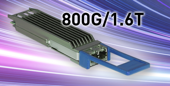
The rapid proliferation of AI, cloud services, and IoT has led to increasingly diversified network usage. This diversification, coupled with the continuous growth in the number of connected devices, has resulted in an exponential increase in data traffic. To be able to handle this increase in data traffic, optical transceivers require technological innovation to achieve ultra-high-speed and high-capacity data transmission. In particular, the optical transceiver market for data centers is seeing the introduction of 800-Gbps (800G) transmission, while the development of the next-generation 1.6-Tbps (1.6T) technology has already begun.
Challenges
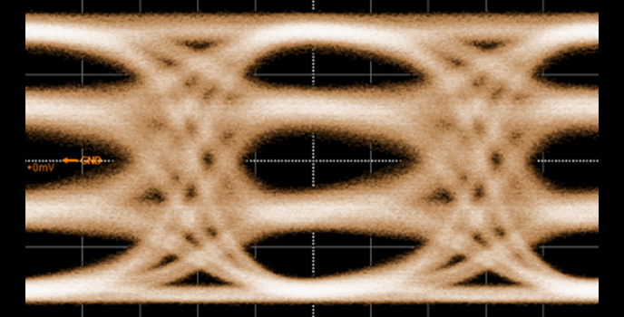
Challenge 1: Severe signal performance requirements for higher speeds
800G/1.6T optical transceivers offer significantly improved data transmission speeds compared to conventional 100G/200G units, but this makes them more susceptible to digital signal jitter and distortion, which can lead to an increase in the Bit Error Rate (BER). In particular, 800G/1.6T optical transceivers with PAM4 can transmit two bits of information per signal (symbol). The narrow spacing between the PAM4 signal levels makes it challenging to ensure a satisfactory signal-to-noise ratio. This makes the signal quality requirements exceptionally stringent.

Challenge 2: Error correction to ensure communication quality
As the transceivers supporting 800GbE and 400GbE with PAM4 are sensitive to signal quality degradation, forward error correction (FEC) technology must be adapted for data transmission. Therefore, verifying both the conventionally evaluated bit error rate and FEC operation must be done using a test signal including jitter and noise.
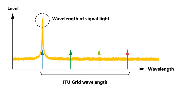
Challenge 3: Wavelength accuracy of signal light
Fiber-optic networks employ wavelength division multiplexing (WDM) technology, which uses signal light of different wavelengths. Optical transceivers must precisely match the wavelength of the signal light to the ITU grid specified in 12.5 to 100 GHz spacing.
Solutions
Solution 1: Quality check of signal waveforms
Anritsu’s Sampling Oscilloscope BERTWave MP2110A is an ideal measurement instrument for the evaluation – in both manufacturing and development - of optical transceivers and modules ranging from 10G to 800G and even up to 1.6T. The MP2110A is an all-in-one instrument that supports evaluations such as PAM4 eye patterns, amplitude, jitter, skew (timing offset), and Transmitter and Dispersion Eye Closure for PAM4 (TDECQ), a metric for the eye-opening rate.
Furthermore, a single MP2110A unit can handle up to four channels, enabling the simultaneous measurement of four lanes of optical transceivers. Additionally, the individual lanes of an optical transceiver can be measured in parallel. This solution is expected to contribute to enhanced production efficiency and reduced manufacturing costs for optical modules.
Leaflet:
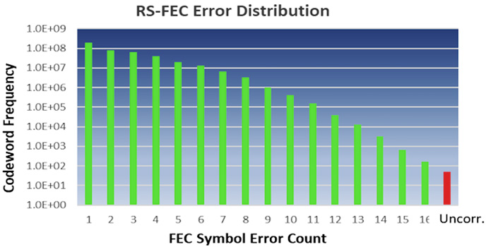
Solution 2: Counting Symbol Errors
400GbE and 800GbE process error correction on PAM4 signals in units of blocks called Codewords.
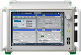
The MP1900A Signal Quality Analyzer counts the number of symbol errors in the Codeword and determines how many of those errors can be corrected.
Application Note:
PAM4 Bit Error Rate Measurement
Leaflet:
Solution 3: Optical Spectrum Measurement
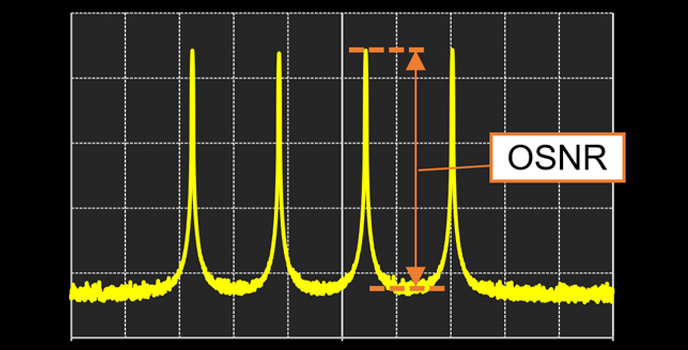
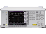
An optical spectrum analyzer displays the wavelengths of the optical transceiver. The optical signal-to-noise level ratio (OSNR) is also an important measurement, since the spacing between signal optical wavelengths is narrower in DWDM.
Web:
High-Speed Spectrum Analyzer MS9740B for Optical Device Evaluation
Resources










Related Products

Contact Us



Copyright 2026