
Optical Fiber Sensing (2)
The previous Optical Fiber Sensing (1) issue explained "point type" sensing; this Optical Fiber Sensing (2) issue explains "distributed type" sensing that can measure at all points along an optical fiber. In distributed-type optical fiber sensing, the optical fiber has a sensor function as well as a function to transmit sensing information.
First, why does the optical fiber itself function as a sensor? This is because when light propagates in a fiber, particles, compositional fluctuations, density distribution, and other internal factors in the fiber cause light scattering, so information is contained in light reflected in the opposite direction (called backscattered light) to the propagating light.
Figure 1 shows the spectrum of backscattered light and what kind of physical information can be obtained from it.
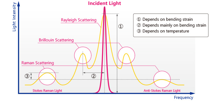
Figure 1: Backscattered Light
The intensity of backscattered light is very low relative to the incident light, but distributed optical fiber sensing performs various types of sensing by reading small changes in this backscattered light.
The following table summarizes distributed-type sensing methods and their features.
| Measurement Method |
Measured Items |
Typical Applications |
Light Source |
| 1. OTDR1) |
Bending strain |
Confirmation and maintenance of optical fiber installation |
LD, DFB-LD6), Gain-chip (pulsing) |
| 2. OFDR2) |
Expansion and contraction strain |
Structural health monitoring and maintenance |
Swept Light Source, Gain-chip (wavelength sweep) |
| 3. B-OTDR3) |
Expansion and contraction strain |
Structural health monitoring and maintenance |
LD, DFB-LD (narrow line width, pulsing) |
| 4. R-OTDR4) |
Temperature |
Plant and pipeline temperature measurement |
LD, DFB-LD, Gain-chip (pulsing) |
| 5. DAS5) |
Vibration, acoustics |
Ground vibration and subsurface structural surveys |
LD, DFB-LD (narrow line width, pulsing) |
1) OTDR: Optical Time Domain Reflectometry or Optical Time Domain Reflectometer
Used to measure Rayleigh scattering intensity and analyze amount of strain
2) OFDR: Optical Frequency Domain Reflectometry
Type of optical interferometry also called FMCW used to measure Rayleigh scattering intensity and analyze amount of strain
3) B-OTDR: Brillouin OTDR
Analyzes amount of strain from frequency shift in Brillouin scattering
4) R-OTDR: Raman OTDR
Analyzes temperature from intensity difference between the Stokes Raman and Anti-Stokes Raman scattering
5) DAS: Distributed Acoustic Sensing
Also called distributed or dispersive acoustic measurement used to measure phase of Rayleigh scattering and analyze vibration
6) DFB-LD: Distributed Feedback Laser Diode
Laser diodes with single oscillating longitudinal mode using Bragg reflections from diffraction grating formed along waveguide
Note: Applications in this table are only representative examples.
Each distributed-type method is described below.
1. OTDR
OTDR is used to check optical fibers and network lines at installation and for measurement during maintenance. Specifically, OTDR analyzes transmission loss (including bending loss) of optical fibers, detects breaks, measures loss at fusion splices and connectors, and locates these points. Figure 2 shows an image of OTDR measurement items and their respective transmission losses.
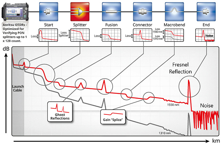
Figure 2: OTDR Measurements and Transmission Losses
OTDR outputs pulsed light into the optical fiber under test, and calculates its position and loss based on the delay time and optical intensity change of the Rayleigh scattered light or Fresnel reflected light returning from the fiber. OTDR uses LDs or gain-chips outputting light pulses at wavelengths in the 1.3-µm and 1.55-µm bands.
Measurable distances range from short distances of less than 10 m to long distances of over 10,000 km for undersea cables; these technologies support our communications-based society.
Click here to learn more about OTDR products.
2. OFDR
OFDR is the only distributed-fiber optic sensing technique using optical interference. It uses a wavelength swept light source with high coherence for high-accuracy measurement of strain with a resolution of 1 µε* and has a spatial resolution of several cm over a range of several hundred meters. The OFDR measurement principle is detailed in the "Advantages of OFDR/Wavelength Swept Light Source" Device Guide.
*Unit of strain where 1 µε corresponds to amount of change in 1 m length expanded or contracted by 1 µm.
OFDR is suitable for dynamic strain measurements over mid-range distances of a few hundred meters. Typical examples are measurement of continuous strain distribution in structures such as windmills, steel towers, and aircraft wings (Fig. 3).
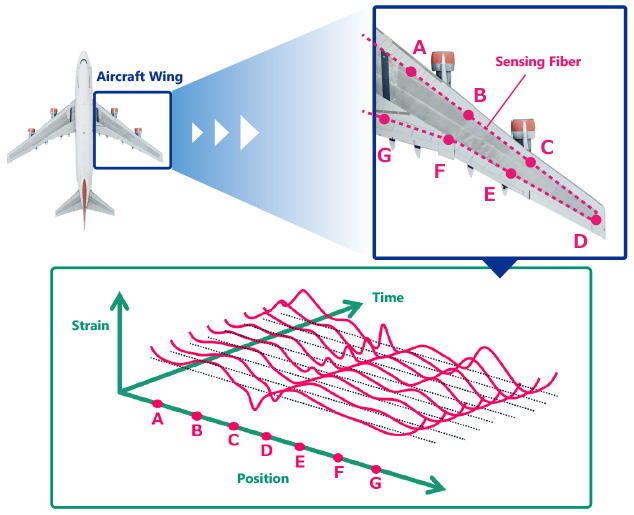
Figure 3: OFDR Measurement Example – Strain Distribution in Aircraft Wing
The sensing method uses a wavelength swept light source in the 1.55-µm band, but light source performance should be considered based on OFDR measurement requirements. For example, a light source with a wider wavelength sweep range is better for higher distance resolution, while a light source with a longer coherence length is better for wider measurement range.
Click here for product information on wavelength swept light sources.
3. B-OTDR
Figure 4 shows the B-OTDR configuration. Light from the light source is split by an optical coupler into two branches, one of which is pulsed by an optical modulator and emitted into the optical fiber under test. The Brillouin scattered light generated in the optical fiber returns in the opposite direction to the outgoing light and is heterodyne-detected using the other light split by the optical coupler. The amount of strain is calculated using signal processing by analyzing the wavelength shift (= amount of frequency shift) of the Brillouin scattered light.
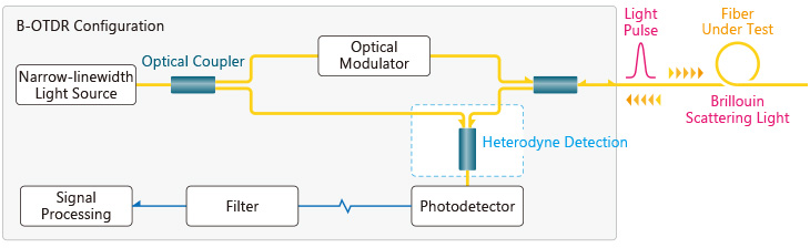
Figure 4: B-OTDR Measurement Configuration
B-OTDR can measure distribution with a distance resolution of about 10 cm and a strain accuracy of 100 µε over a wide range of several tens of km. Although this method has a wide measurement range, measurement requires several minutes for averaging the Brillouin scattered light. Consequently, B-OTDR is unsuitable for dynamic measurements and is used for static strain distribution and displacement measurements.
B-OTDR uses a pulsed light source with a narrow linewidth; 1.5-µm band DFB-LDs with a relatively high optical output are suitable.
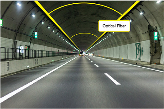
Figure 5: Example of B-OTDR Measurement – Monitoring Tunnel Deformation
4. R-OTDR
Figure 6 shows the R-OTDR configuration. Light emitted from the light source is pulsed by an optical modulator and emitted into the optical fiber under test. Raman scattered light generated in the optical fiber returns in the opposite direction of the outgoing light and is separated into Raman-scattered Stokes light and anti-Stokes light by the distributor and received. Temperature is calculated by analyzing the difference in intensity between this Stokes and anti-Stokes light.
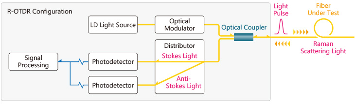
Figure 6: R-OTDR Measurement Configuration
R-OTDR can measure temperature distribution over a range of 100 km with a distance resolution of a few meters. The pulse light emission interval varies with distance and required accuracy. R-OTDR requires the same averaging process as B-OTDR, and real-time temperature measurement is difficult.
R-OTDR uses a pulsed light source; DFB-LDs and gain-chips in the 1.5-µm band with relatively high optical output are suitable.
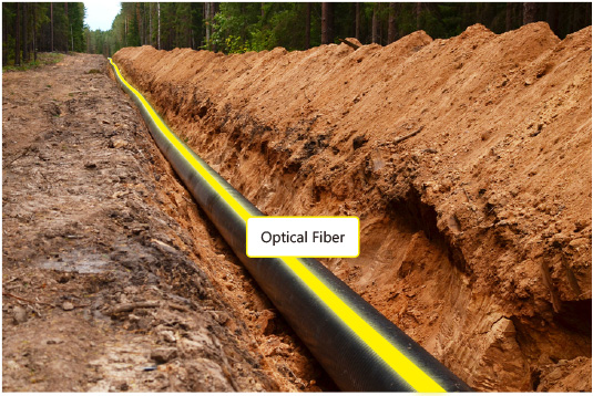
Figure 7: Example of R-OTDR Measurement – Monitoring Pipeline Temperature
Click here for product information on DFB-LD.
5. DAS
DAS is a method for measuring the distribution of optical fiber vibrations.
Figure 8 shows the measurement configuration. One of the two branches of light from the light source is pulsed and emitted. Rayleigh scattered light from the optical fiber is heterodyne-detected by the other light, and the phase variation is analyzed and calculated as vibration data.
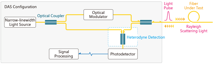
Figure 8: DAS Measurement Configuration
This sensing method can sample at a high speed of 10 kHz over a range of several tens of kilometers, making it applicable for a wide range of fields, such as vehicle traffic analysis, vibration measurement for underground equipment maintenance, hydraulic fracture monitoring during shale gas and oil drilling, and seismic measurement. It uses a narrow-linewidth pulsed light source; DFB-LDs in the 1.5-µm band with a relatively high optical output are suitable.
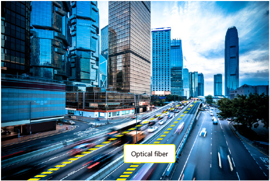
Figure 9: Example of DAS Measurement – Traffic Volumes and Analysis(using underground dark fiber)
Anritsu has a full range of light sources for optical fiber sensing. For product information on our SLDs, DFB-LDs, and Wavelength Swept Light Sources, visit our Optical Sensing for Industry web page.
If you have any questions, please contact us via the Support tab at the above link.
