
Device Development History
Optical Device (5) – Wavelength Swept Light Source –
This issue features the story of Anritsu's wavelength swept light source product development, which is expected to be applied as a light source for sensing applications in a wide range of fields.
Wavelength Swept Light Source Development Background
In the late 1980s, it was reported that micromachining technology based on semiconductor processes could be used to create micron-scale machines. This was called MEMS (Micro Electro-Mechanical Systems) and various mechanisms were proposed. Acceleration and pressure sensors for automobile were the first MEMS applications, and low cost was achieved by creating a membrane structure on a silicon substrate and forming electronic circuits on the same substrate. Today, MEMS are used widely in a variety of automotive sensors as well as in medical applications such as blood-pressure monitors. They are also used in inkjet printer heads, which are now common in most households. Even in optics, MEMS has a wide range of applications, including displays with integrated MEMS micro-mirrors, switches for optical communications and attenuators.
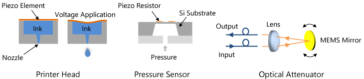
MEMS Application Examples
Therefore, MEMS has attracted attention from the beginning as a promising technology for its wide range of applications. Anritsu had previously commercialized a scanning laser diameter-measuring system for optical fibers and other wire materials, using a magnetically driven tuning-fork optical scanner. We applied MEMS technology to the scanner and began studying ways to improve its performance. Applying simulation technology for electromagnetic field analysis, one of our strengths, was an advantage. In 1997, we received technical support from a pioneering university laboratory in the field and began developing MEMS technology. This laboratory had its own processing equipment and was a lively place with researchers dispatched from various domestic and overseas companies.
Investigation of the MEMS drive system is a major application issue. Comb-type actuators are based on the principle that electrostatic force is generated by applying voltage to opposing electrodes, and this is the primary method of operation. However, due to our lack of experience in the basic technology, we did not achieve the targeted performance and discontinued the project. Therefore, we switched to a method using mechanical resonance by magnetic force.
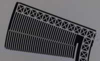
Prototype Actuator
Development of Optical Scanner
Figure (a) shows a schematic of a MEMS mirror manufactured from silicon substrate. The silicon micromirror (approx. 6 × 8 mm) in the center is supported by two beams. A magnetic material called permalloy is attached to the back at two points, and mechanical resonance motion is generated by applying periodic signals to electromagnets placed near the mirror. Figure (b) is an example of the resonant frequency simulation. The thickness and length were determined by considering the resonant frequency of the reciprocating motion of the mirror and the strength of the mirror. Figure (c) shows an actual optical scanner with an electromagnet behind the mirror.
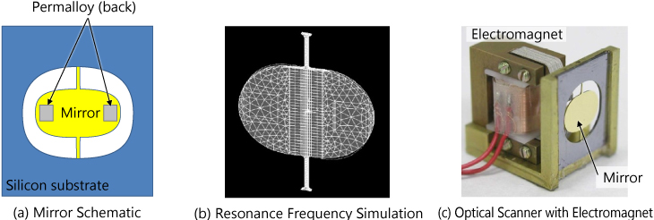
Optical Scanner
The MEMS mirror fabrication is outlined here. Aluminum is deposited on both sides of the silicon substrate, and the back is patterned and etched using photolithography technology to create holes for fixing the permalloy. The face side is etched using a special deep etching tool called deep RIE (Reactive Ion Etching) to form mirrors, and chromium and gold are deposited to increase reflectivity. The developed optical MEMS scanner consumes 1/10 the power and is half the size of the tuning-fork scanner used in our previous products, and has achieved almost twice the resolution performance, contributing to product differentiation when incorporated in a new scanning laser diameter-measuring system.

Schematic of mirror manufacturing process
Wavelength Swept Light Source Applications
Optical fiber sensor technology is useful in countering natural disasters by monitoring slopes for landslides and flooding river levels, as well as for monitoring the integrity of large structures, such as bridges and buildings. Fiber Bragg Grating (FBG) sensors have attracted attention for their accuracy and wide range of applications. FBG sensors work on the principle that the wavelength of reflected light changes according to the external stress or temperature change applied to a fiber diffraction grating. A broadband light source, such as a halogen lamp or SLD (Super Luminescent Diode), or a wavelength swept light source can be used. In particular, the wavelength swept light source method provides high performance by focusing optical energy, and we developed this light source using our optical scanner technology. As shown in the top right figure, the laser part consists of a semiconductor laser diode (LD) with antireflection coating on one side, an isolator and a collimating lens, all nitrogen sealed with a fiber output. The filter consists of a MEMS scanning mirror and a Littmann diffraction grating, and a resonator is formed between the LD and MEMS mirror. This achieved a wavelength sweep speed from 1520 to 1580 nm of 1.4 msec.
Furthermore, we developed the SF3041A/3011A FBG sensor monitor in 2007, which integrates this light source with an optical circulator, photodetector, driver, and signal processing board. This device has successfully detected FBG fiber strain signals with high sensitivity, demonstrating that it can be used in the actual field. For example, we confirmed that it can monitor the displacement of FBG sensors installed on the seafloor from a remote location on land.
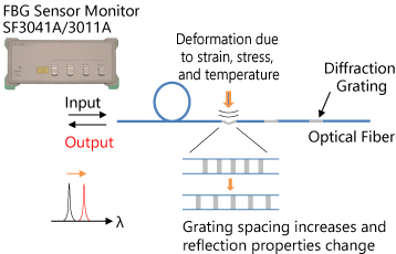
Principle of FBG Sensor Monitor
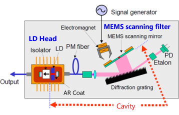
Configuration of Wavelength Swept Light Source
Development of New Wavelength Swept Light Source
Despite its small wavelength fluctuation, our first-generation wavelength swept light source had a large optical output variation due to multimode oscillation. Therefore, a new wavelength swept light source module was designed in 2011 to downsize the entire light source and suppress mode changes during wavelength sweeping. As a result, the current product achieves mode-hop-free and single-mode oscillation over the entire sweep range and has been adopted in ophthalmic medical equipment. In addition, the FBG fiber sensor monitor has been redesigned. Compared to the former SF3041A/3011A, the new AR4041A/4011A models are 1/50th the size of the light source unit, and the signal processing circuit has also been greatly reduced. Both the device volume and mass have been reduced by about 40%.
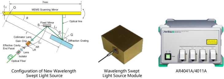
We reported these results at several academic conferences and received various enquiries from major general contractors and heavy industry manufacturers, who actually used this light source for R&D. However, we did not have sufficient support systems to continue this business over the long term, so we focused our resources on the main unit of the wavelength swept light source. The current line of commercial light sources includes benchtop, built-in unit, and module types to meet various needs. They are all capable of phase-continuous and mode-hop-free sweeps, and the coherence lengths exceed 100 m under certain conditions. We can demonstrate their application to actual optical interferometry systems such as OFDR (Optical Frequency Domain Reflectometry); contact us if you are interested.
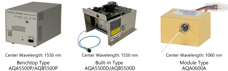
Current Wavelength Swept Light Source Line
Anritsu’s wavelength swept light source originated from an optical scanner based on MEMS technology, and resulted in our current line of high-performance products after many years of prototyping and studying light sources and systems. Optical sensing using wavelength swept light sources is applicable to many fields, including OCT measurement in medicine and chemistry, surface profile measurement in industry, in-line inspection, vibration measurement, and infrastructure integrity monitoring. We receive enquiries from various fields, such as monitoring flying objects, managing building structures, measuring the profile and internal structure of parts, jewelry, etc.
We position this light source as a core product in optical sensing to help create a safe and secure society by growing the optical sensing market.
This episode concludes the series on the development of our device. Thank you for reading and click the following link to our Anritsu Sensing & Devices Company website if you would like to learn more.
